
The superhet radio or to give it its full name the superheterodyne receiver is one of the most popular forms of receiver in use today. Virtually all broadcast radios, televisions and many more types of receiver use the superhet or superheterodyne principle. First developed at the end of the First World War, with its invention credited to the American Edwin Armstrong, the use of the superhet has grown ever since the concept was first discovered.
Mixing
The idea of the superhet revolves around the process of mixing. Here RF mixers are used to multiply two signals together. (This is not the same as mixers used in audio desks where the signals are added together). When two signals are multiplied together the output is the product of the instantaneous level of the signal at one input and the instantaneous level of the signal at the other input. It is found that the output contains signals at frequencies other than the two input frequencies. New signals are seen at frequencies that are the sum and difference of the two input signals, i.e. if the two input frequencies are f1 and f2, then new signals are seen at frequencies of (f1+f2) and (f1-f2). To take an example, if two signals, one at a frequency of 5 MHz and another at a frequency of 6 MHz are mixed together then new signals at frequencies of 11 MHz and 1 MHz are generated.

The signals generated by mixing or multiplying two signals together
Concept of the superheterodyne receiver
In the superhet or superheterodyne radio, the received signal enters one input of the mixed. A locally generated signal (local oscillator signal) is fed into the other. The result is that new signals are generated. These are applied to a fixed frequency intermediate frequency (IF) amplifier and filter. Any signals that are converted down and then fall within the passband of the IF amplifier will be amplified and passed on to the next stages. Those that fall outside the passband of the IF are rejected. Tuning is accomplished very simply by varying the frequency of the local oscillator. The advantage of this process is that very selective fixed frequency filters can be used and these far out perform any variable frequency ones. They are also normally at a lower frequency than the incoming signal and again this enables their performance to be better and less costly.
To see how this operates in reality take the example of two signals, one at 6 MHz and another at 6.1 MHz. Also take the example of an IF situated at 1 MHz. If the local oscillator is set to 5 MHz, then the two signals generated by the mixer as a result of the 6 MHz signal fall at 1 MHz and 11 MHz. Naturally the 11 MHz signal is rejected, but the one at 1 MHz passes through the IF stages. The signal at 6.1 MHz produces a signal at 1.1 MHz (and 11.1 MHz) and this falls outside bandwidth of the IF so the only signal to pass through the IF is that from the signal on 6 MHz.

The basic concept of the superhet radio
If the local oscillator frequency is moved up by 0.1 MHz to 5.1 MHz then the signal at 6.1 MHz will give rise to a signal at 1 MHz and this will pass through the IF. The signal at 6 MHz will give rise to a signal of 0.9 MHz at the IF and will be rejected. In this way the receiver acts as a variable frequency filter, and tuning is accomplished.
Images
The basic concept of the superheterodyne receiver appears to be fine, but there is a problem. There are two signals that can enter the IF. With the local oscillator set to 5 MHz and with an IF it has already been seen that a signal at 6 MHz mixes with the local oscillator to produce a signal at 1 MHz that will pass through the IF filter. However if a signal at 4 MHz enters the mixer it produces two mix products, namely one at the sum frequency which is 10 MHz, whilst the difference frequency appears at 1 MHz. This would prove to be a problem because it is perfectly possible for two signals on completely different frequencies to enter the IF. The unwanted frequency is known as the image. Fortunately it is possible to place a tuned circuit before the mixer to prevent the signal entering the mixer, or more correctly reduce its level to acceptable value.
Fortunately this tuned circuit does not need to be very sharp. It does not need to reject signals on adjacent channels, but instead it needs to reject signals on the image frequency. These will be separated from the wanted channel by a frequency equal to twice the IF. In other words with an IG at 1 MHz, the image will be 2 MHz away from the wanted frequency.
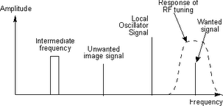
Using a tuned circuit to remove the image signal
Complete receiver
Having looked at the concepts behind the superheterodyne receiver it is helpful to look at a block diagram of a basic superhet. Signals enter the front end circuitry from the antenna. This contains the front end tuning for the superhet to remove the image signal and often includes an RF amplifier to amplify the signals before they enter the mixer. The level of this amplification is carefully calculated so that it does not overload the mixer when strong signals are present, but enables the signals to be amplified sufficiently to ensure a good signal to noise ratio is achieved.
The tuned and amplified signal then enters one port of the mixer. The local oscillator signal enters the other port. The local oscillator may consist of a variable frequency oscillator that can be tuned by altering the setting on a variable capacitor. Alternatively it may be a frequency synthesizer that will enable greater levels of stability and setting accuracy.
Once the signals leave the mixer they enter the IF stages. These stages contain most of the amplification in the receiver as well as the filtering that enables signals on one frequency to be separated from those on the next. Filters may consist simply of LC tuned transformers providing inter-stage coupling, or they may be much higher performance ceramic or even crystal filters, dependent upon what is required.
Once the signals have passed through the IF stages of the superheterodyne receiver, they need to be demodulated. Different demodulators are required for different types of transmission, and as a result some receivers may have a variety of demodulators that can be switched in to accommodate the different types of transmission that are to be encountered. The output from the demodulator is the recovered audio. This is passed into the audio stages where they are amplified and presented to the headphones or loudspeaker.

Block diagram of a basic superheterodyne receiver
The diagram above shows a very basic version of the superhet or superheterodyne receiver. Many sets these days are far more complicated. Some superhet radios have more than one frequency conversion, and other areas of additional circuitry to provide the required levels of performance. However the basic superheterodyne concept remains the same, using the idea of mixing the incoming signal with a locally generated oscillation to convert the signals to a new frequency.
Mixing
The idea of the superhet revolves around the process of mixing. Here RF mixers are used to multiply two signals together. (This is not the same as mixers used in audio desks where the signals are added together). When two signals are multiplied together the output is the product of the instantaneous level of the signal at one input and the instantaneous level of the signal at the other input. It is found that the output contains signals at frequencies other than the two input frequencies. New signals are seen at frequencies that are the sum and difference of the two input signals, i.e. if the two input frequencies are f1 and f2, then new signals are seen at frequencies of (f1+f2) and (f1-f2). To take an example, if two signals, one at a frequency of 5 MHz and another at a frequency of 6 MHz are mixed together then new signals at frequencies of 11 MHz and 1 MHz are generated.
The signals generated by mixing or multiplying two signals together
Concept of the superheterodyne receiver
In the superhet or superheterodyne radio, the received signal enters one input of the mixed. A locally generated signal (local oscillator signal) is fed into the other. The result is that new signals are generated. These are applied to a fixed frequency intermediate frequency (IF) amplifier and filter. Any signals that are converted down and then fall within the passband of the IF amplifier will be amplified and passed on to the next stages. Those that fall outside the passband of the IF are rejected. Tuning is accomplished very simply by varying the frequency of the local oscillator. The advantage of this process is that very selective fixed frequency filters can be used and these far out perform any variable frequency ones. They are also normally at a lower frequency than the incoming signal and again this enables their performance to be better and less costly.
To see how this operates in reality take the example of two signals, one at 6 MHz and another at 6.1 MHz. Also take the example of an IF situated at 1 MHz. If the local oscillator is set to 5 MHz, then the two signals generated by the mixer as a result of the 6 MHz signal fall at 1 MHz and 11 MHz. Naturally the 11 MHz signal is rejected, but the one at 1 MHz passes through the IF stages. The signal at 6.1 MHz produces a signal at 1.1 MHz (and 11.1 MHz) and this falls outside bandwidth of the IF so the only signal to pass through the IF is that from the signal on 6 MHz.
The basic concept of the superhet radio
If the local oscillator frequency is moved up by 0.1 MHz to 5.1 MHz then the signal at 6.1 MHz will give rise to a signal at 1 MHz and this will pass through the IF. The signal at 6 MHz will give rise to a signal of 0.9 MHz at the IF and will be rejected. In this way the receiver acts as a variable frequency filter, and tuning is accomplished.
Images
The basic concept of the superheterodyne receiver appears to be fine, but there is a problem. There are two signals that can enter the IF. With the local oscillator set to 5 MHz and with an IF it has already been seen that a signal at 6 MHz mixes with the local oscillator to produce a signal at 1 MHz that will pass through the IF filter. However if a signal at 4 MHz enters the mixer it produces two mix products, namely one at the sum frequency which is 10 MHz, whilst the difference frequency appears at 1 MHz. This would prove to be a problem because it is perfectly possible for two signals on completely different frequencies to enter the IF. The unwanted frequency is known as the image. Fortunately it is possible to place a tuned circuit before the mixer to prevent the signal entering the mixer, or more correctly reduce its level to acceptable value.
Fortunately this tuned circuit does not need to be very sharp. It does not need to reject signals on adjacent channels, but instead it needs to reject signals on the image frequency. These will be separated from the wanted channel by a frequency equal to twice the IF. In other words with an IG at 1 MHz, the image will be 2 MHz away from the wanted frequency.

Using a tuned circuit to remove the image signal
Complete receiver
Having looked at the concepts behind the superheterodyne receiver it is helpful to look at a block diagram of a basic superhet. Signals enter the front end circuitry from the antenna. This contains the front end tuning for the superhet to remove the image signal and often includes an RF amplifier to amplify the signals before they enter the mixer. The level of this amplification is carefully calculated so that it does not overload the mixer when strong signals are present, but enables the signals to be amplified sufficiently to ensure a good signal to noise ratio is achieved.
The tuned and amplified signal then enters one port of the mixer. The local oscillator signal enters the other port. The local oscillator may consist of a variable frequency oscillator that can be tuned by altering the setting on a variable capacitor. Alternatively it may be a frequency synthesizer that will enable greater levels of stability and setting accuracy.
Once the signals leave the mixer they enter the IF stages. These stages contain most of the amplification in the receiver as well as the filtering that enables signals on one frequency to be separated from those on the next. Filters may consist simply of LC tuned transformers providing inter-stage coupling, or they may be much higher performance ceramic or even crystal filters, dependent upon what is required.
Once the signals have passed through the IF stages of the superheterodyne receiver, they need to be demodulated. Different demodulators are required for different types of transmission, and as a result some receivers may have a variety of demodulators that can be switched in to accommodate the different types of transmission that are to be encountered. The output from the demodulator is the recovered audio. This is passed into the audio stages where they are amplified and presented to the headphones or loudspeaker.
Block diagram of a basic superheterodyne receiver
The diagram above shows a very basic version of the superhet or superheterodyne receiver. Many sets these days are far more complicated. Some superhet radios have more than one frequency conversion, and other areas of additional circuitry to provide the required levels of performance. However the basic superheterodyne concept remains the same, using the idea of mixing the incoming signal with a locally generated oscillation to convert the signals to a new frequency.


0 Comments:
<< Home | << Add a comment